T-base Lathe
Spring 2018
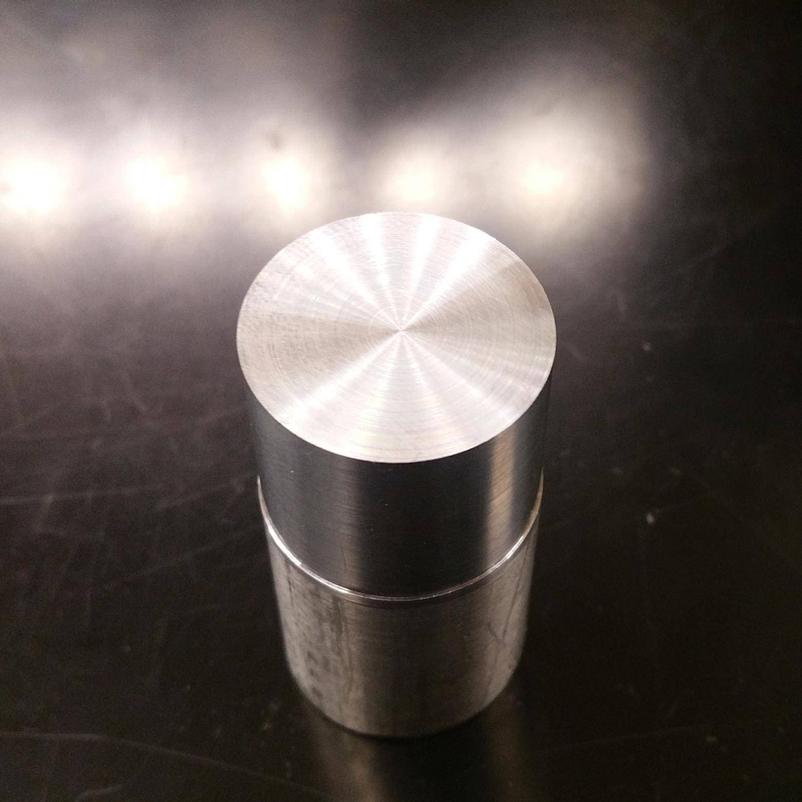
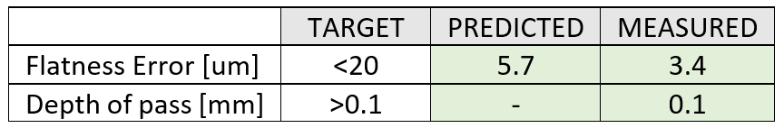
The goal of this project was to design, build and test a T-base lathe. T-base lathe are characterised by having its axes not stacked on each other. This layout is usually used to machine lenses or any element that requires high flatness accuracy and repeatability. My lathe achieved a flatness error below 5um over a 5/8" diameter aluminum part for a depth of cut of 100um.
Throughout the precision machine design class (2-77) taught by Prof. Alex Slocum, this lathe was designed and built sequentially, starting by the the linear-motion axes, then the lead screws, and then a full lathe error model. Each module was tested seperately during the design process before a final assembly and testing. Additional detail as well as the final report can be downloaded below.
Contributions
System Modelling - Error budgeting/apportionment
Mechanical Design
Manufacturing (milling, lathe, waterjet)
Testing
Design Process
The design processed that was used for this machine was the following:
- Overall machine specification and error apportionment
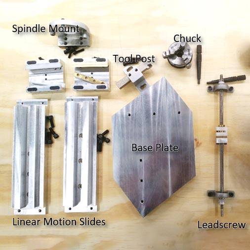
- Divide the machine into several modules (linear axes, lead screw, tool post and motor mount)
- Lay all the modules in a structural loop
- Construct the entire error budget and set each module’s functional requirements
- For each module: Concept Generation/ Analytical Model/ Concept Selection/ Manufacturing/ Testing/ Loop Closure on Analytical Model
- Assemble, test the entire machine and compare the result to the overall machine error model
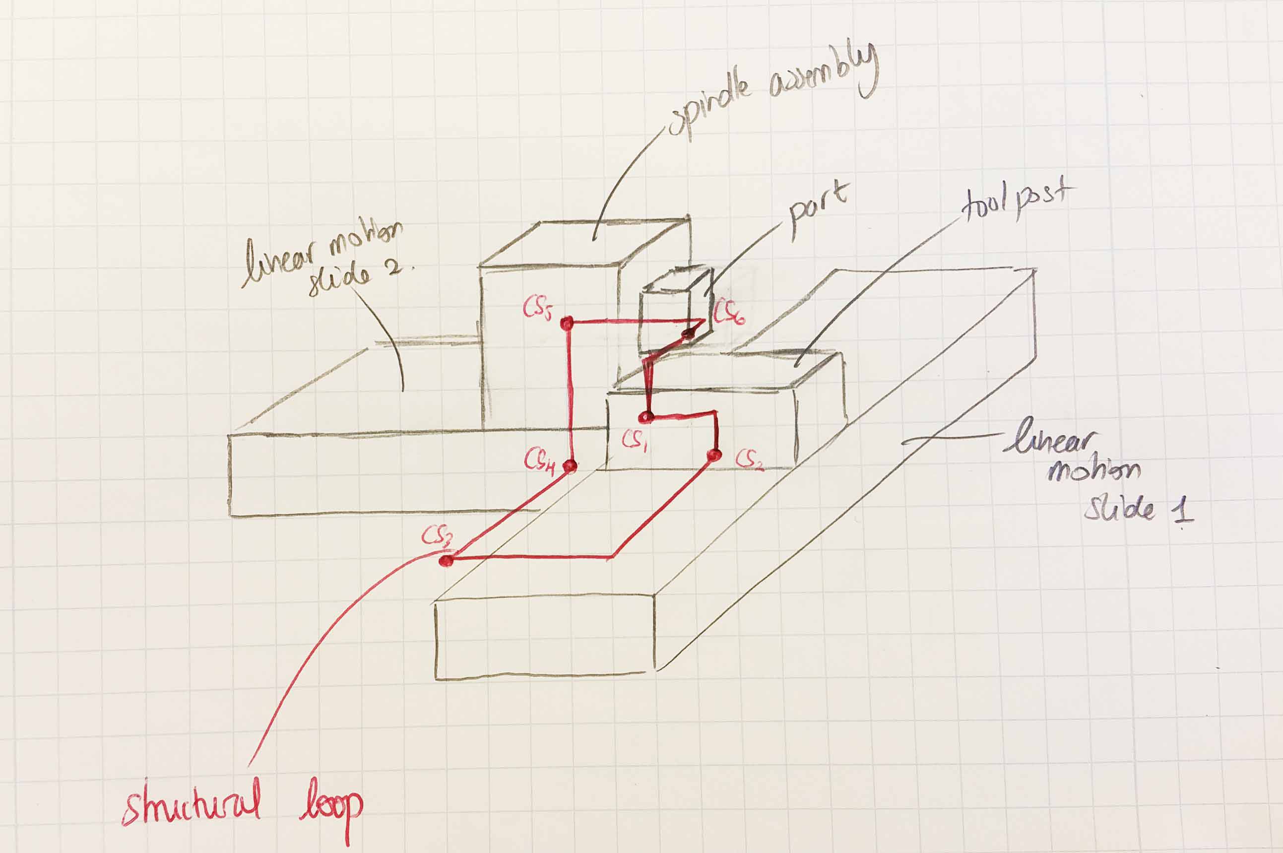
Drawing of T-based Lathe Concept
Linear Motion Slide (LMS)
DESIGN
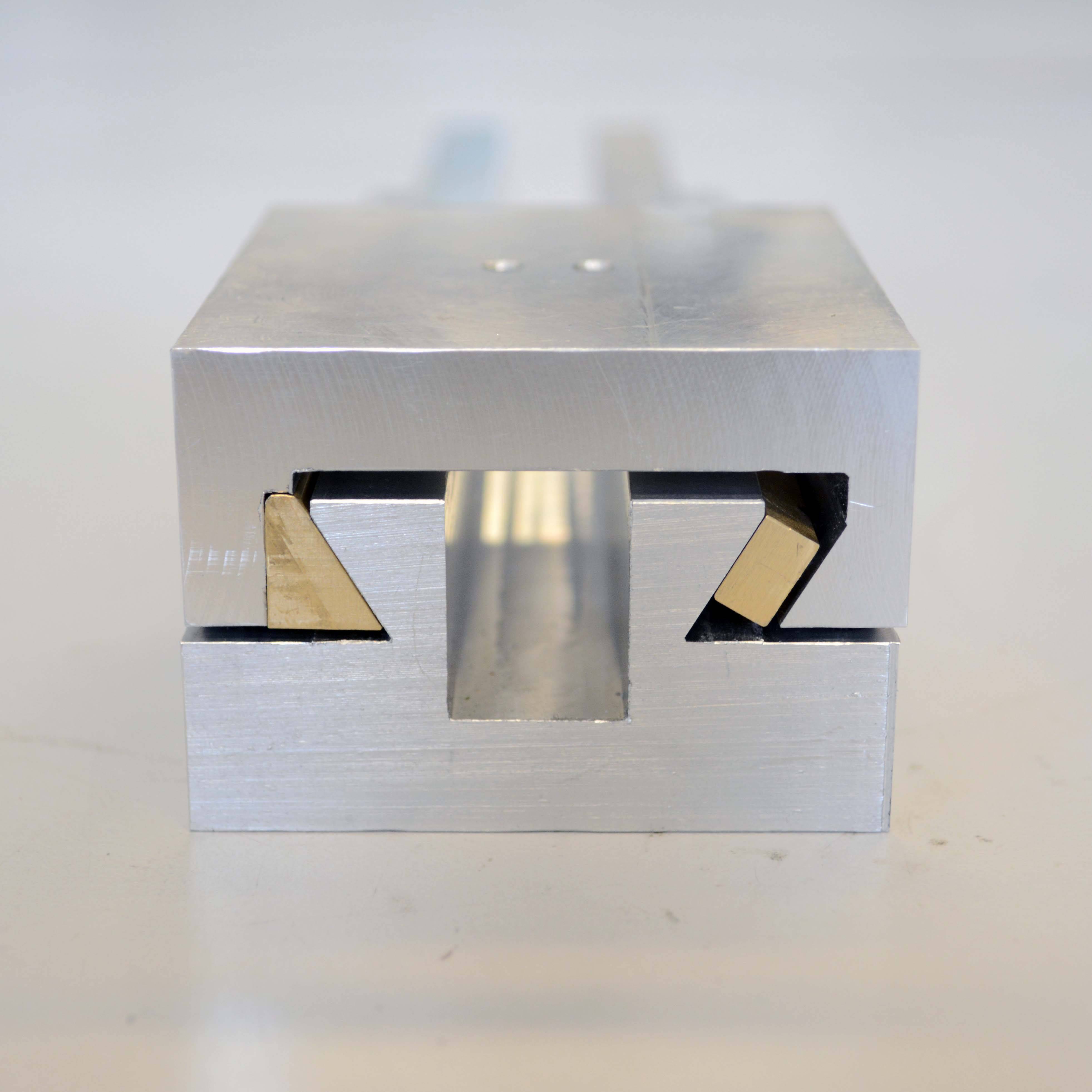
After exploring different concepts that would be suitable for a T-base lathe including, twin rails, dovetails, box ways, roller/rails as well as ball/groove designs I chose the dovetail LMS. It is a simple design that requires only one preload mechanism, yields high stiffnesses and a design that I have never built before.
To fulfill the design intent, I listed the functional requirements that the LMS had to satisfy (see design spreadsheet):
- Travel Range of 100mm
- Facing operations with a flatness of 100um over 20mm
- Small torque to drive the LMS (less than 500 Nmm, easy to turn the handle by hand)
- Not fail under cutting loads
ANALYSIS
From the Kalpakjian, Manufacturing Engineering and Technology I derived the cutting forces on a lathe for aluminum. I applied beam bending theory, beam shearing, and beam axial compression to do the stiffness analysis of the LMS (see design spreadsheet):
- In more depth, for the angular stiffnesses, I assumed a linear load distribution on the contact areas, found the pressure magnitude and computed the angle deflection assuming a distributed stiffness on the contact areas.
- Next, I did an HTM analysis on the LMS, the carriage and the tool to find the errors gains from the LMS deflection on the tool tip, putting each reference frame at the center of stiffness of each element considered.
- For the accuracy of the system, I used the stiffness calculations, HTM analysis and cutting loads to compute the tool deflection under roughing cutting loads and geometric errors (flatness from manufacturing process).
- For the repeatability, I estimated it from the wear equation and PV analysis as well as the change in tool deflection when the cutting loads change up to 50% (using the same error gain analysis from the HTM analysis).
- From the analysis, I was able to size each component in the dovetail system: rail size, carriage, bearing pads, gibs, preload mechanism (Belleville washers) to fulfill all the functional requirements.
CONCEPT EXPLORATION
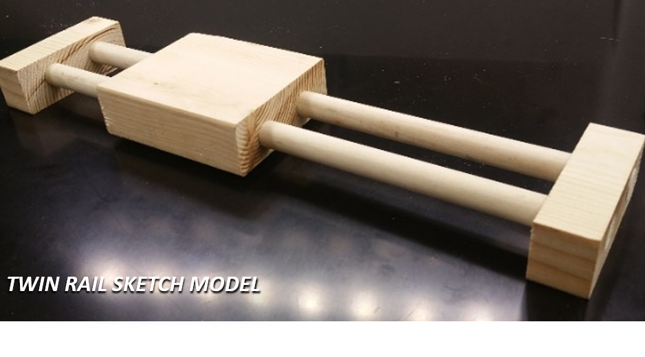
I then explored different concepts that would be suitable for this application including, twin rails, dovetails, box ways, roller/rails as well as ball/groove designs. I then selected the dovetail rails and twin rails concept to do the analytic model and predict their performance.
From the analysis, I was able to understand the trade-offs of each design.
- The dovetail design is very stiff but will be very sensitive to the manufacturing since any “bump” on the rail of the carriage will impose a large normal force, thus the force required to move the linear slide will increase drastically. Also preloading the system with gibs will not be an easy task.
- The twin rail design is much more compliant especially in roll unless the footprint (size) of the LMS is increased significantly (diameter of the rails and spacing between the rails). However, the compliance of the system and the quasi-kinematic design make it easier to manufacture, assemble and less sensitive to geometric errors of the LMS. In addition, having the tool closer to the center of stiffness (and increasing the tool height to give some clearance for cutting the part) will help alleviate the error motions from the roll stiffness of the LMS.
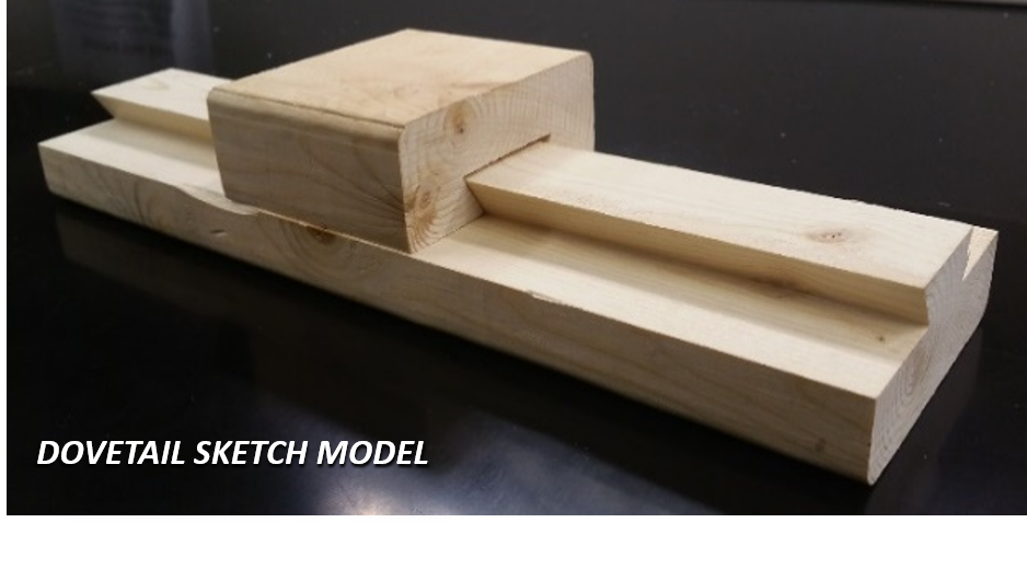
I then went on and made a sketch models of each design and tested them in terms of stiffness and geometric errors to validate my analytical model. From the analysis and the sketch models, I selected the dovetail LMS design for the ease of preloading the rails, the increased overall stiffness of the system.
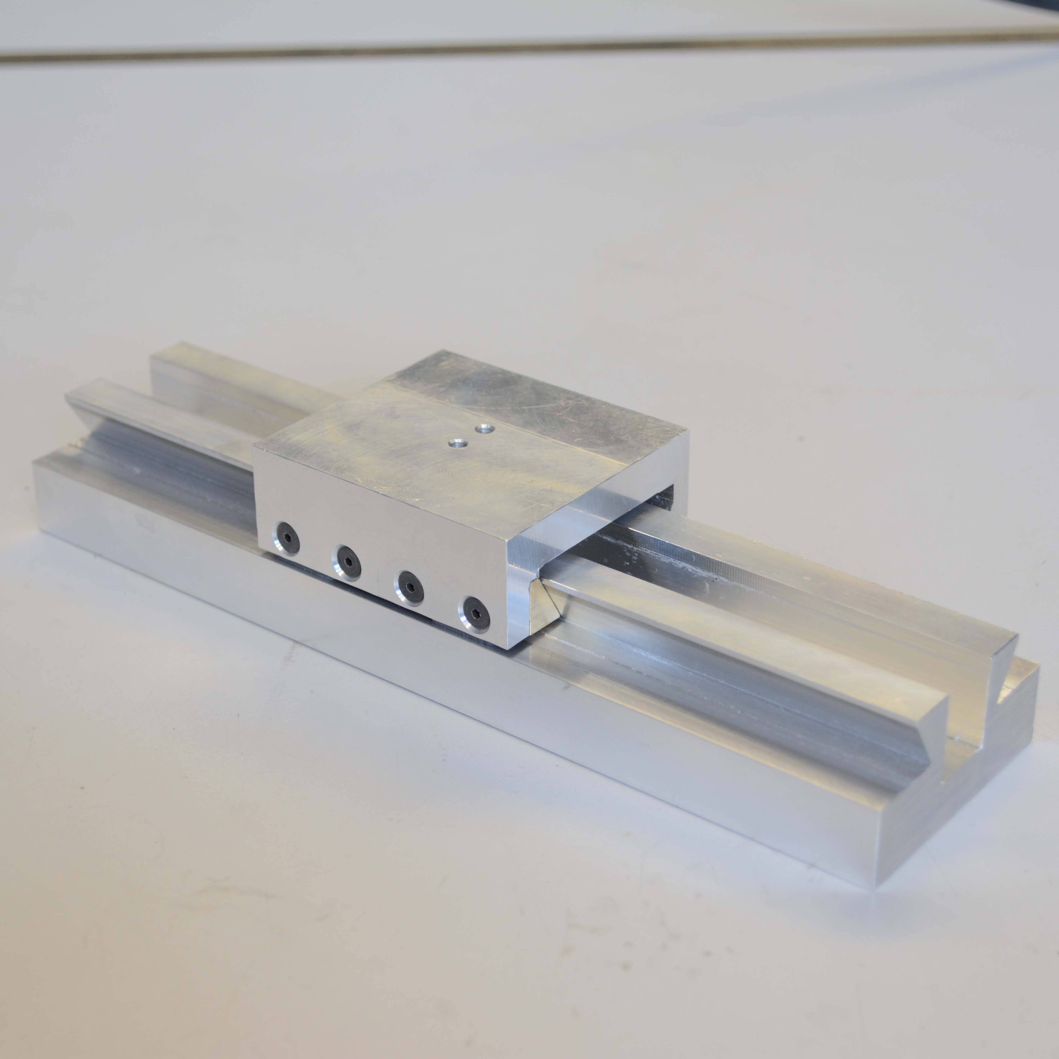
FABRICATION
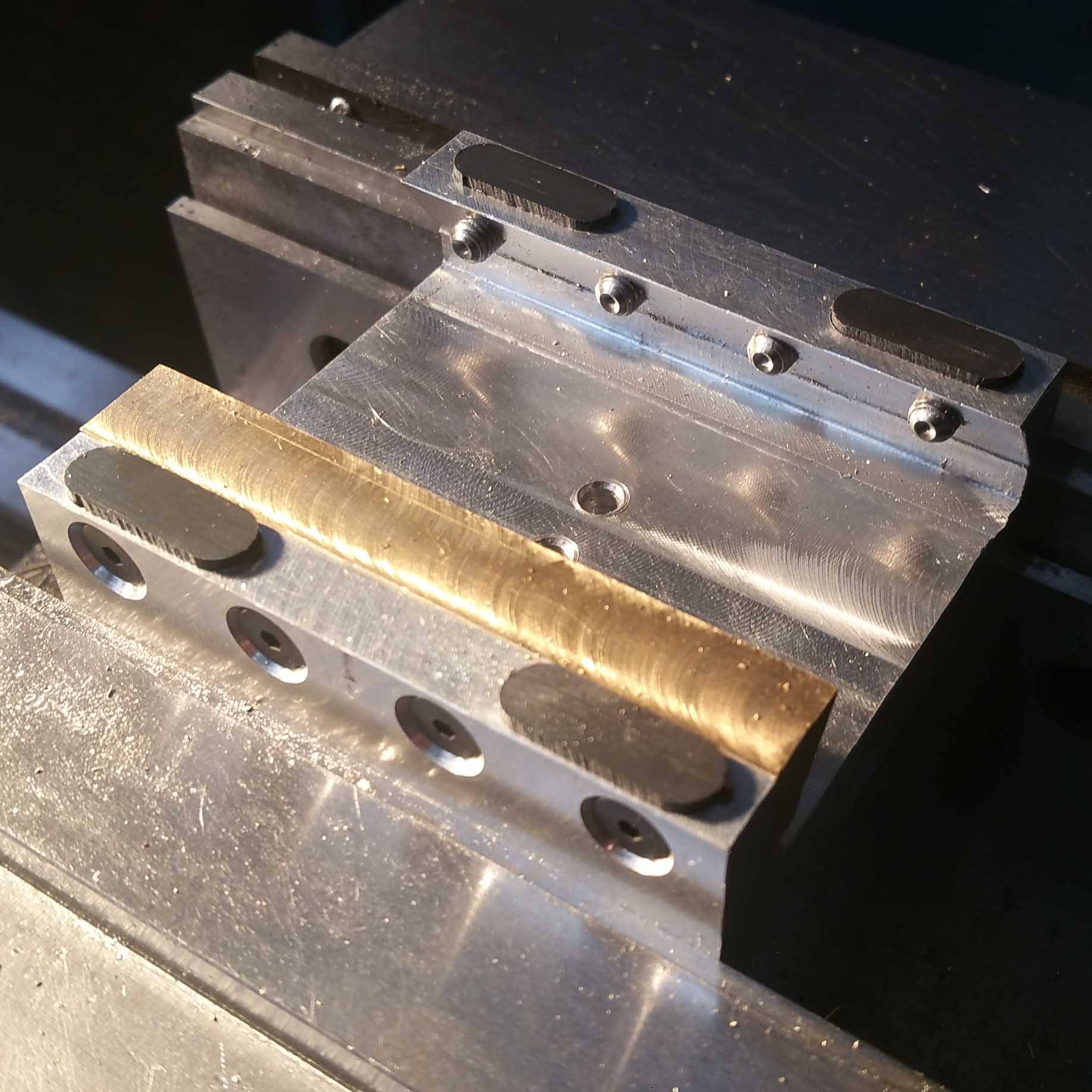
Most of the fabrication was done using a mill. The carriage and the rail were made from aluminum stock, using a dovetail cutter. The gibs were made from brass stock. The teflon pads were made on the waterjet and press-fitted in the carriage. For the dovetail brass gib, I first made it using angle blocks but during assembly, there was an angular mismatch from the dovetail brass gib and the rail (line contact). To fix that mismatch, I fixtured the gib in the carriage and used the dovetail cutter to get the right angle. For the next iteration, I will definitely machine the dovetail gib having it bolted on the carriage.
TESTING
The LMS was tested for angular and translation stiffness, as well as angular accuracy to ensure that it satisfied all the functional requirements (see design spreadsheet that includes all the experimental results).
STIFFNESS TESTS:
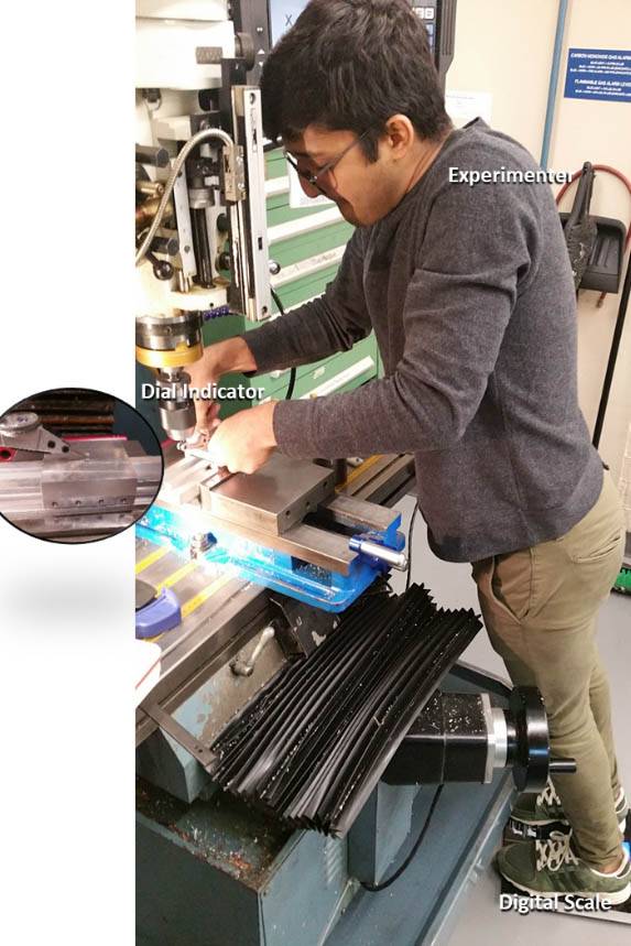
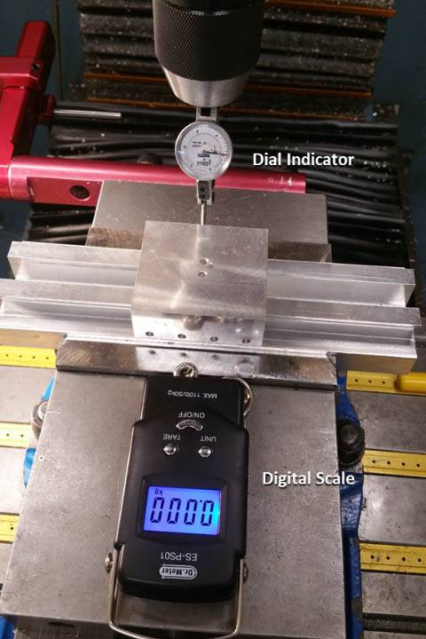
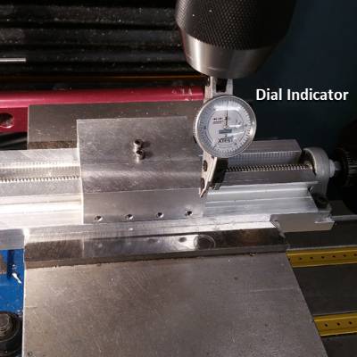
For the Y and Z stiffness the LMS was positioned on the mill and the deflection was measured using a dial indicator. For the Y stiffness a digital scale was used to load the LMS but for the vertical stiffness body weight was used to load the LMS and a weight scale was used to record the body weight load on the LMS.
The measure Z-stiffness (vertical) was of 7.7 N/um which matches the predicted value of 11 N/um (stiffness mainly from Teflon bearing pads). On the contrary, the measured Y-stiffness of 24.3 N/um was almost an order of magnitude less from the predicted value of 423 N/um. The measured value is also several orders of magnitude higher than the preload springs stiffness. I added some oil on the rails to get a sense on the contact area between the dovetail gib and the rail, which turned out to be a small patch rather than the entire area. This contact area difference explains the reduced stiffness value.
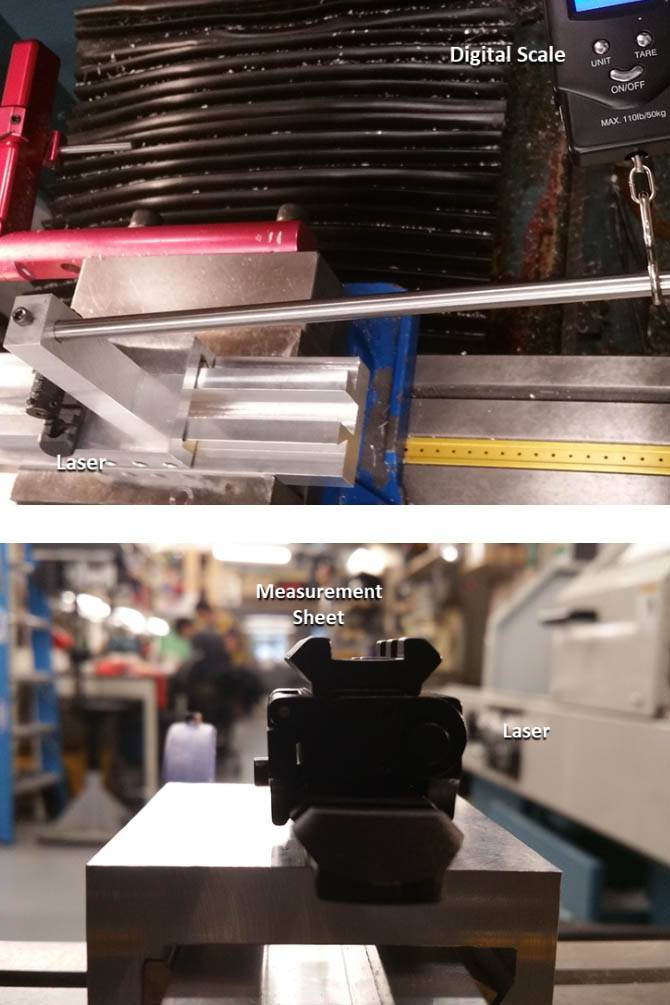
For the angular stiffnesses, I had incorporated a mount to apply the loads at a set distance from the carriage and measured the motion of the laser pointer on a sheet 16.8m away from the carriage.The predicted angular stiffnesses were derived using the translation stiffnesses so measured the pitch, and roll stiffness 5.9 and 4.7 Nm/mrad matched the predicted values of 7 Nm/mrad. Similarly, since the yaw stiffness is derived from the y-stiffness there was a discrepancy between the measure yaw stiffness 13.7 Nm/mrad and the predicted yaw stiffness of 173 Nm/mrad. However, if we use the measured y-stiffness to derive the yaw-stiffness we get a value of 11 Nm/mrad which is much closer to the measured yaw stiffness.
ANGULAR GEOMETIC ACCURACY OF THE LMS:
To test the angular geometric errors of the LMS, it was fixtured on the mill, mounted with a laser and the LMS was moved back and forth and the laser motion was marked on a sheet 16.8 m away from the carriage. The measured angular errors were:
- Yaw Error: 0.5mrad --> 27.5um tool tip associated error (predicted 56 um)
- Pitch Error: 0.9mrad --> 31.5um tool tip associated error (predicted 25 um)
- Roll Error: 0.1mrad --> 3.5um tool tip associated error (predicted 25 um)
The predicted values were computed assuming an accuracy of 0.001” on the mill (flatness error). The manufactured LMS fulfilled the functional requirements in terms of geometric errors.
DISCUSSION
I am very satisfied with the dovetail LMS and its performance, knowing that it only requires less than 10N when preloaded to move back and forth. Oiling the rails and using Teflon pads definitely helped getting such low friction on the slide. Using more compliant gibs such as delrin might be easier to manufacture and improve the lateral and yaw stiffnesses since it will conform the the rail after being preloaded.
Leadscrew
DESIGN
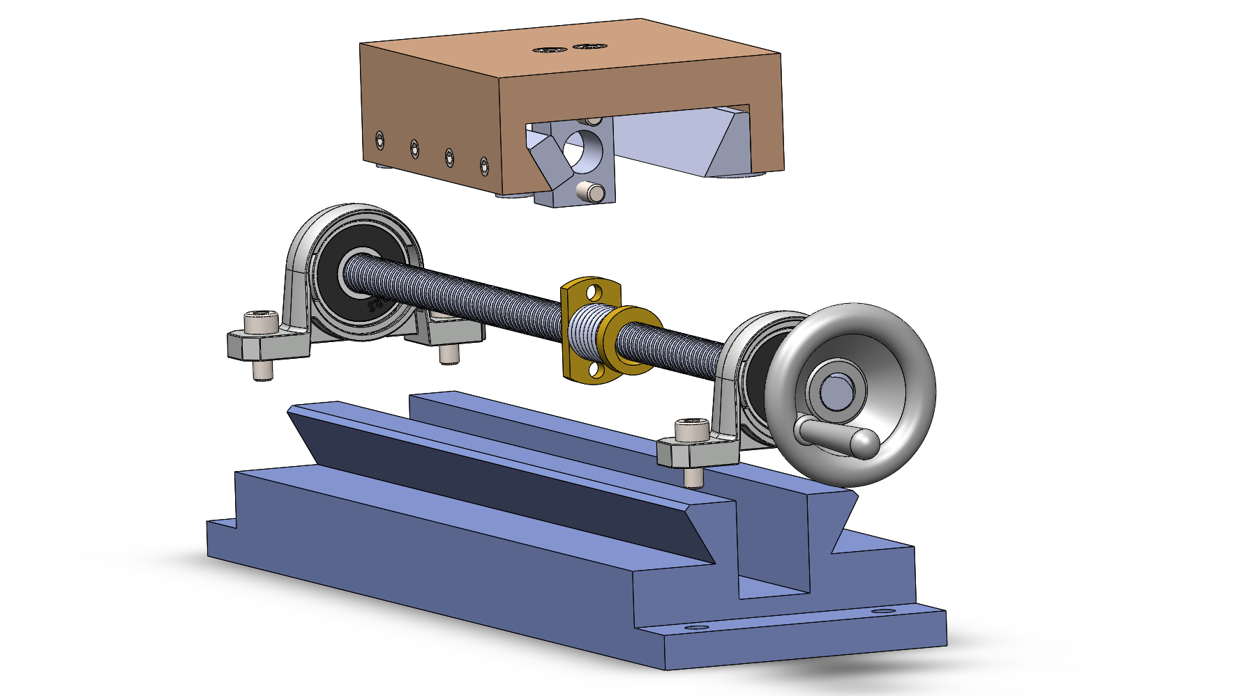
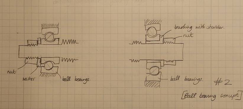
The leadscrew is designed to be used for actuating the LMS for a desktop T-based lathe. I explored different concepts that would be suitable for this application considering different bearing layouts, leadscrew size, and materials. After considering, bushing, thrust bearings and ball bearings concepts with different layouts, I settled on a ball bearing concept with a back to back configuration (see sketch on the right)
To fulfill the design intent, I listed the functional requirements that the leadscrew had to satisfy (see design spreadsheet):
- Travel Range of 100mm
- Comfortable driving torque less than 500 Nmm (about 1kg at 50mm, cheap stepper motor rated torques)
- Resolution less than 100 um (considering stepper motor resolution of 2 deg)
- Axial Stiffness above than 0.5 N/um (under finishing pass cutting loads less than 20 um deflection)
- Safety factor of 2 against failure from buckling, yielding, fatigue.
- No backlash in the nut
- Thermally stable design (even though the leadscrew won’t be running at high speeds)
ANALYSIS
For the analysis, I looked at (see design spreadsheet):
- The required driving torque using the screw equation, cutting loads ,friction of the carriage on the rails and friction at the bearing blocks on the leadscrew.
- The axial and bending stiffness of the leadscrew (beam under compression and pin-pin beam), as well as the bushings and bearings (hertz contact).
- Look at the backdriveability (screw equation condition)
- Stress analysis on the leadscrew from cutting loads and misalignment.
- Geometric errors due to misalignment of the leadscrew (force displacement on a pin-pin beam, resulting in a load on the carriage --> displacement at the tool tip)
- Load induced errors at the tool tip due to leadscrew’s assembly axial stiffness and cutting loads.
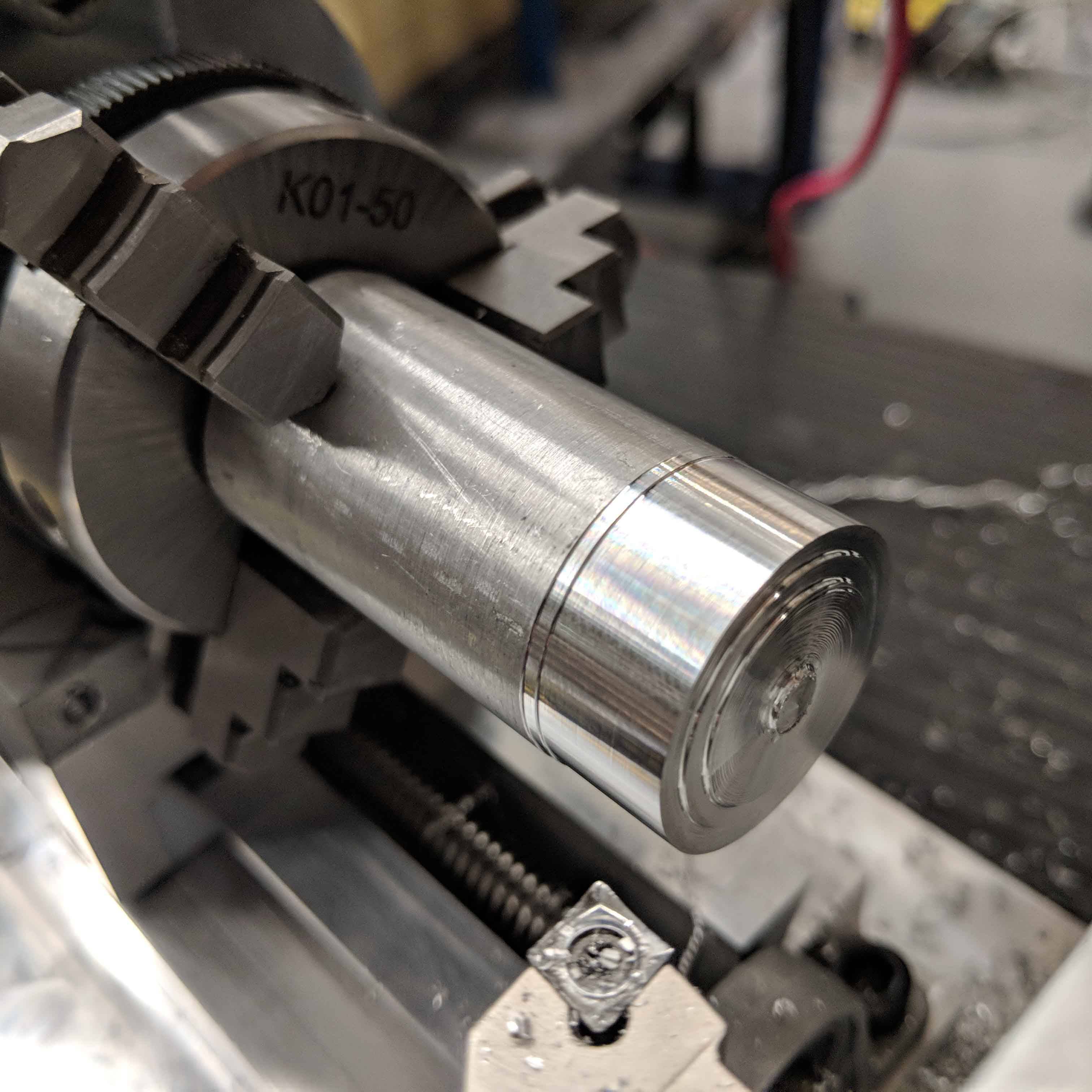
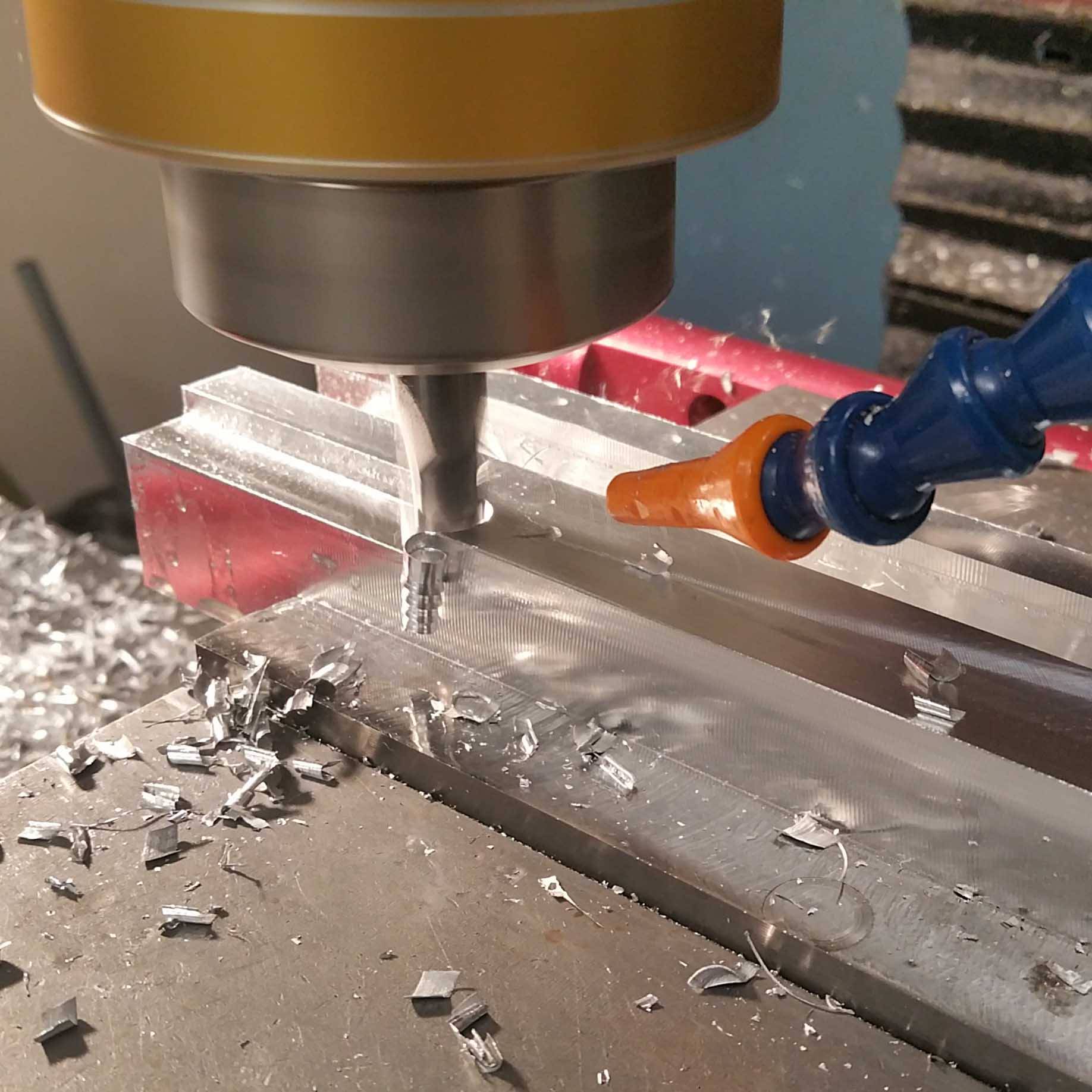
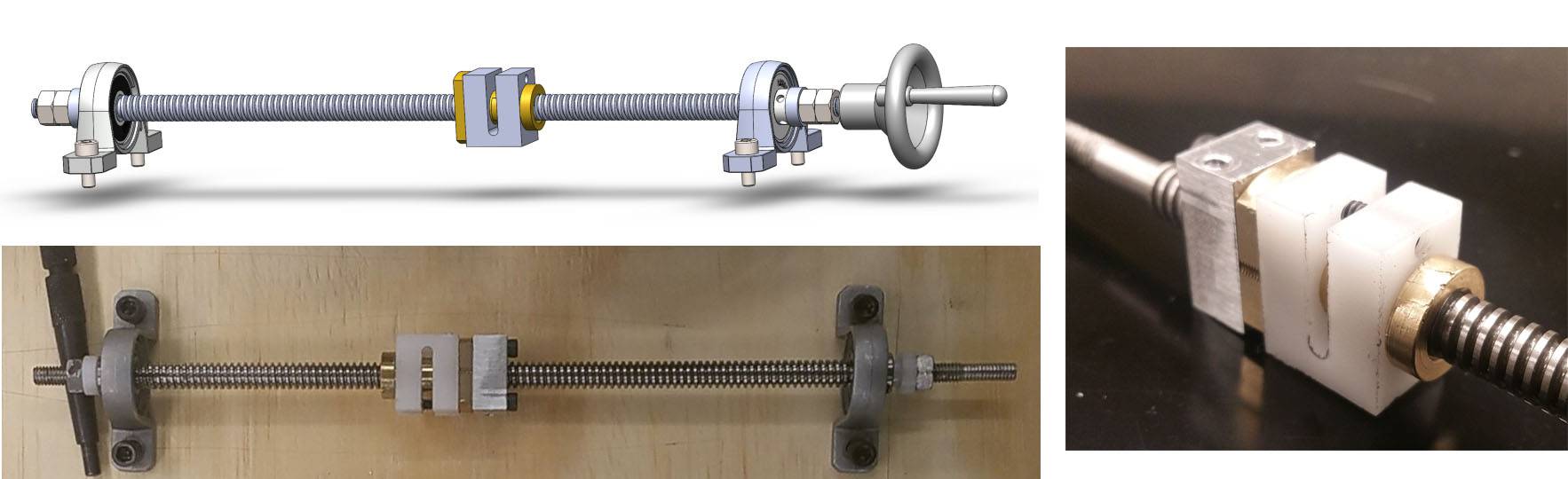
FABRICATION
Most of the fabrication was done using the lathe. The bushings were made on user a delrin rod and the leadscrew was also turned down on the lathe. The leadscrew was indicated using a dial indicator to find the high points so that when it had to be rechucked for the second operation we could place the high points at the same location (minimizing radial error from 3-jaw chuck). The threads on the leadscrew where then added using a M6x1.0 die.
TESTING
For this module, I tested the following characteristics: Axial stiffness of the leadscrew assembly, Driving torque to move the carriage, Carriage error motions Z- Axis and Y-axis, Lead Error (see design spreadsheet that includes all the experimental results).
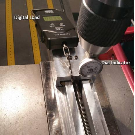
STIFFNESS TESTS:
For this measurement, I used a digital load scale, a dial indicator (0.0002” resolution) with the assembly fixtured in the mill. The measured stiffness was 2.6 N/um which matches the predicted stiffness of 5.6 N/um.
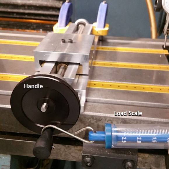
DRIVING TORQUE
For this measurement, I used a spring scale on the handle (52 mm in diameter) and recorded the load at which the handle starts to move. This measurement actually considers the static friction and not the dynamic one making it a more conservative value. The measured torque 128 Nmm matched the predicted one of 145 Nmm. The LMS is very easy to move!
GEOMETRIC ERRORS
For the lead error as well as the carriage error motions measurements, I used the dial indicator with the LMS fixtured on the mill. I had the carriage travel and measured the error on the dial indicator. For the lead error, I couldn’t measure any error on the dial indicator for half a revolution. Similarly for the geometric errors, they were on the order of the rail flatness errors measured last week ( about 30 um) showing that any misalignment or bowing in the leadscrew didn’t affect the motion of the carriage significantly.
DISCUSSION
The bearing layout and modified leadscrew fulfill the design requirements. The custom anti-backlash system enables the cutting tool to cut in both direction withtout losing the preload nor increasing the driving torque.
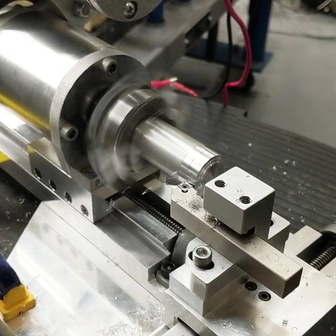
Full lathe Assembly

TESTING
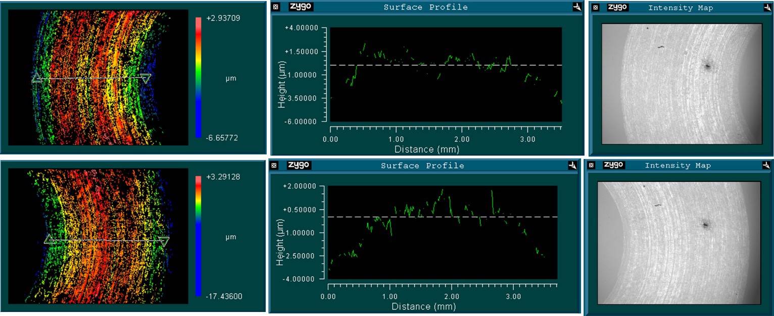
The flatness of the 0.1mm test cuts were then measured on a ZYGO white light interferometer, exhibiting a maximum height difference on the face of 3.4 ± 0.2 microns, and a misalignment between the two linear motion axes of 0.89 ± 0.05 mrad matching our design requirements and our predictions of 5.7 microns load induced errors.
DISCUSSION
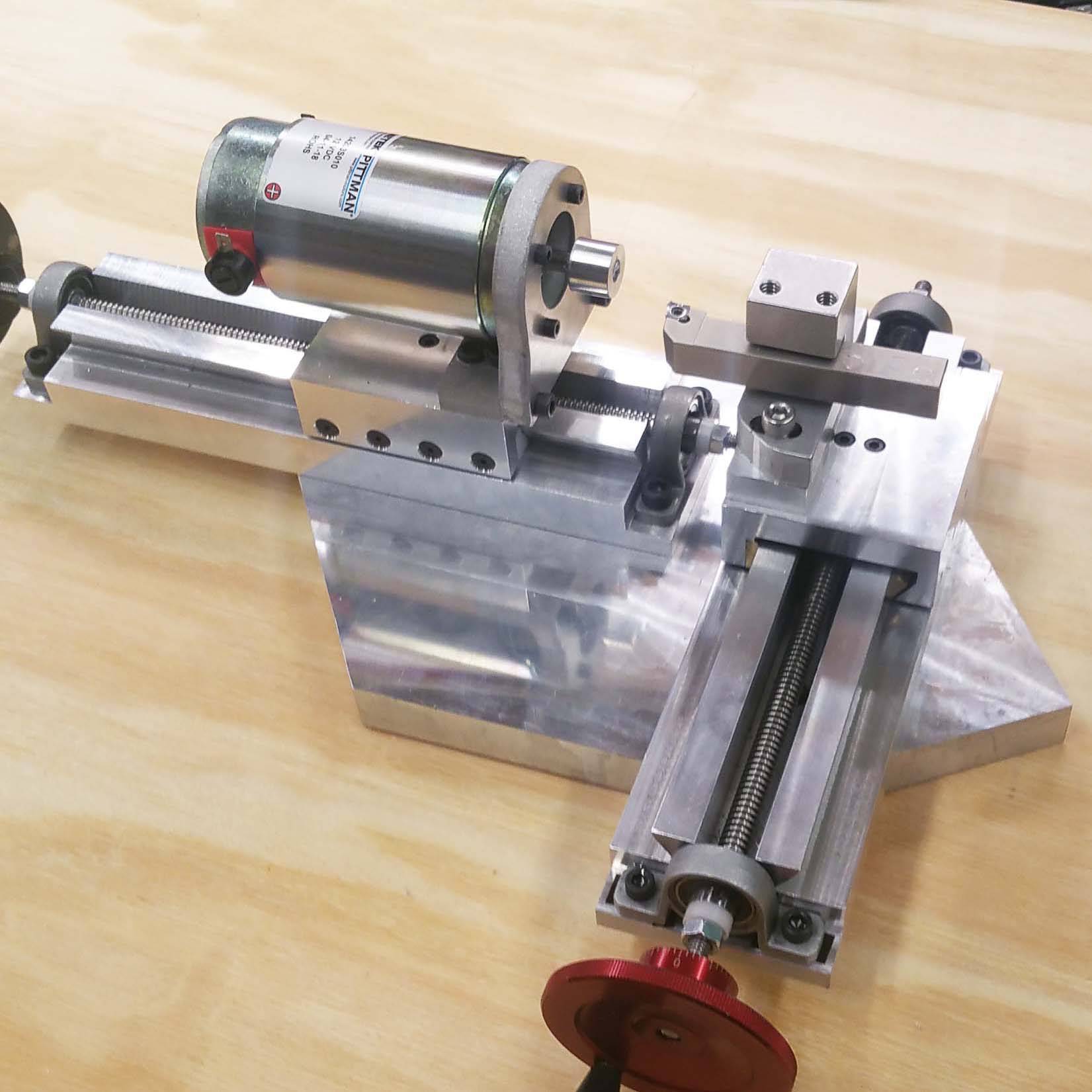
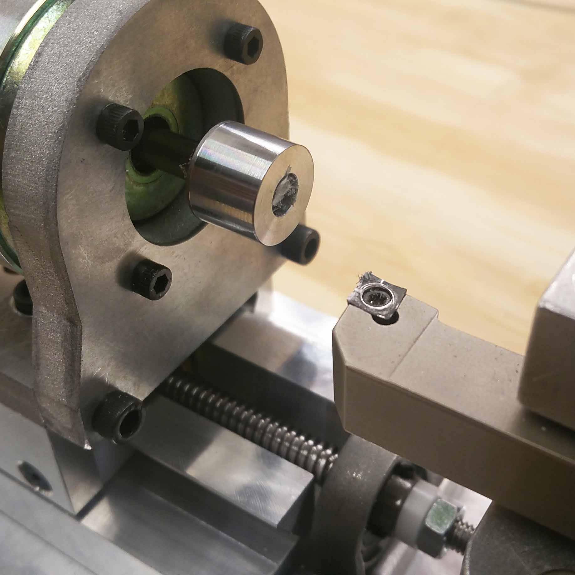
The T-based lathe performed as expected and this project was valuable in teaching me a deterministic and rigorous design process that includes: defining the functional requirements, concept generation, thorough analysis with a clear statement of the assumptions, testing and reflecting on the model. However, the current spindle assembly would need to be replaced by an electric motor running an actual spindle with a chuck or collet to allow us to not only face the part but also turn the diameter.
Here after is the T-based lathe updated with an improved spindle assembly with a chuck.